Sunday 28 May 2017

4 input and 4 seperate output pre-amp

This is another microphone pre-amp project from me. I've done it long time ago but didn't have enough time to write down and share all of the data. So, here i'm posting the schematic along with all details including my YouTube video.
The schematic is given below:
The potentiometer at the output is used to set the gain of the output while the other potentiometer is the fixed on board variable resistor what you'll use to set the peak LED indication. Once it is done you can enclose the board inside the metal casing (and connect ground cable with the metal housing/enclosure).

The first two transistors are c1815 which are lowest noise transistors are cascaded in amplifier arrangement. Both transistor stages are amplifying their input signals. 

The peak transistor 2n3904 detects the current at the output and when base of this transistor is high it will act as a switch to turn on the LED to indicate the peaking signal of your output. This peaking can be set by adjusting tha 20K variable as i mentioned above. 
The capacitor at its input is acting as DC-blocking while the other cap between base and ground is used to hold the base high for a while. 1k resistor at the base is basically for the protection of the transistor's base to prevent high current to flow to the base that can result in blown 2n3904.

The power section is filtered as can be seen in RC filter arrangement mode.
I posted below the video of how i built every thing:


I hope you guys will love this project. If any kind of help is required i'm always available to help you out. You can comment on my YouTube video (posted above) or my facebook page.
Good Luck and Stay blessed. I'll make detailed video about the circuit soon.

Thursday 3 November 2016

DC Single Supply to DC Dual Supply Conversion

There are several method to do. One is to use oscillator (that uses a transformer) to convert DC into AC then this AC is fed to a centertapped transformer. So when we'll be having another center tapped transformer we can use bridge rectifier and capacitors to take the Dual output.

There is also another method using a Timer IC that is 555 timer.
Circuit diagram taken from datasheet is given below also available on google.


The first method can provide lot of more power while the second arrangement is for low power applications. Also the voltage is limited to 15v. But at least 15v is enough to power op-amps and several other applications.
Now generating -ve voltage can also be done using any operational amplifier with some specifications like a TDA2030 which is dual voltage operated Integrated Chip used for the HIFI audio amplification. Given below is the circuit for TDA2030 dual voltage supply from single voltage source.
The pin 1 is the non-inverting input and so, when we see the feedback (shown by a green trace) between pin 2 & 4 we can easily recognize that it is in the voltage follower mode. The resistors 2.2k are used to keep the same voltage on the GND (from input) or -Vout. So, the voltage follower in this case turns the level of the output pin 4 as 0 which become refernce node for output GND.
Given below is the pinout configuration of TDA2030. 
The other amp ic's can be used for this purpose. But again this method is for the low power amplification the output of the input voltage will never be the same in this case but it will be divided as there is a voltage divider section in the circuit shown above.
The Vout=Vin/2 like if the input voltage was 9v then output will be 4.5v dual.

All of the above circuits are efficient and they do work and tested practically by me. Because i believe that everything a human design doesn't mean that it will always work.


Friday 30 October 2015

Build a Studio Condenser Microphone (DIY) Part-1

I posted about a simple circuit in the previous post. But after some experiments of different capsules i have found some difference in their working. And so, there must be changes in the circuit. I got a 16mm small diaphragm capsule and i wanted to test it. But the 10k resistor was creating a little noise. So i designed this circuit:
 Here you can see the one phase was needed for the unbalanced output. I don't know why but a 30M Ohm resistor was the only suitable resistor to power the capsule. And none other were working and i'm just trying to figure it out why. 

So the phase is taken from FET and then fed to the preamp circuit. Nothing very special here. This is just like the previous one. 
By decreasing the value of 30M Ohm resistor you can make the other non electret microphone capsule work with it.

If you have an unexpected noise then you may need to place a diode between gate and the source (ground) of FET.

So how we can have a balanced phantom powered microphone ?
As i told you about the phase that is taken from source of FET. We need to have another phase from drain too. So that we'll be having two outputs. Here is the diagram :
The both output is fed to the base of both PNP transistor. I was about to use BC557 but i found that they are little noisy. You may not measure that tiny noise but that is disturbing. So i replaced these with A1015 which are specially made for a low noise amplifier and i have found a good use of them here ;)
Pin 2 and Pin 3 are filtered by their caps 0.022uf which is a 22nf to avoid noise.
A 9v Zener diode is used as a shunt regulator to supply 9v to FET and transistors because for this circuit 9v is sufficient. Variation in voltage can also create noise.
For the phantom power filtration we have a RC flter circuit in it. If you observe we have 10uf after 9v Zener Diode and then 100 Ohm resistor and then again 100uf cap. And you may want to try different values of these caps but i have already played with them and found that these are the pretty standard & suitable values.

Have a wonderful project. Hang on in the part-2 i'm gonna post the practical work.

Monday 27 April 2015

Condenser Microphone Capsule (Driver Circuit)

I received many request on powering a condenser microphone capsule and to use it direct with PC soundcard.I searched the whole internet and found that there is no method to drive the "Small Diaphragm" condenser microphone capsule without 48v phantom power. There are many other circuits that requires phantom power to power up the capsule. And also these circuits has the output of an XLR jack that can be connected to the intefaces. But the problem is that not everyone have the interface. So, if you wanna play with a capsule without spending money on buying some interfaces or phantom power you can use my circuit which is given below:

Yes, you don't need to use a 1G Ohm resistance which is almost in every circuit. Your microphone is really gonna work.
Most common examples of the capsule that are available in the market or online market are:
  • TSB160a
  • TSB165a
If the capsule is back electrek, you dont need to supply power to it. But if its not then you can add a seperate battery like shown in  the diagram below: 

VALUES OF COMPONENTS:

So, if you have any other capsule that isn't back electrek (That doesn't has charge on back plate) you need to supply it power. For the small diaphragm capsule. The value of R1 at 1.5v is typically 4.7k 10k and for 9v it should be 5.6k to 12k.
A Pretty Standard value for C1 is 0.1uF. But you can change it depends upon your capsule and your requirements.

NOTE:

Noise is the biggest issue while playing with any material related to audio. So, to prevent the noise just take a suitable metal housing for your capsule and connect the circuit's GND terminal with the housing. This will minimize the noise.
GOOD LUCK ..! :)
See ya. In the next project (IA).

Monday 29 December 2014

Build a Guitar Tremolo Effect Pedal Easily

Hello..!
So, Who wants to build a tremolo effect box? for your instruments such as Guitars, pianos etc.
Today i am going to show you how you can build your own tremolo guitar effect pedal.
First of all take a look of the circuit diagram below:
So, In the diagram above, you can see that i am using NE555 timer IC for making the LED blink with a constant speed that is adjustable with the help of potentiometer. The speed for blinking of LED can be adjusted by changing the resistance between 2nd,6th with 7th pins of timer IC.
Also you can see that the 2nd LED that is in the shell with LDR has another potentiometer to control its brightness. That is called the depth. Because, if the LED shines brighter and strikes more light on LDR, its resistance will become almost zero and that effects the sound. You don't need to connect the switch in difficult way as we do in other stomp-box. Because in this circuit it isn't necessary.
When LED Strikes light on LDR the input signals goes to ground and we don't hear the sound in that time interval. When LED is off the signals goes to output. That is why you hear a "Wah Wah" sound effect similar to Tremolo/Phaser LED and LDR.

POSSIBLE QUESTION You may have about it.!

What thing i can use for the shell.?

You can use the plastic cover, hard plastic pipe piece or the plastic holder of 3.5mm stereo jack. Or any other thing.

What is the purpose of other LED?

Other LED find its name. It is "Monitor LED" that is fit to the project box in such a way you can see it to know its blinking speed and brightness (that is related to the shell LED which is inside the project box)

Don't you have a video tutorial? 

Yes we have a video tutorial in which i am sharing my idea about how i built it.

I hope you 'll love it and i believe that you 'll make it wonderful. Have a Good Project..!
See Ya...!
___________________
Next Project : Building a Studio Condenser Shaped Mic (With Dynamic Pickup Pattern) having 3.5mm microphone jack for PC and Laptop. Hang On...!!

Sunday 11 May 2014

Build a 20W Guitar Amp (DIY)

The IC LA4440 was very useful and easy to use it as an amplifier DIY project. We build a guitar amplifier using this basic schematic from datasheet.
 
As you can see its a basic circuit. So we added a tone control at the audio input to control bass,treble and volume. Use our filter circuit we have given in the previous posts to join it with power supply to avoid the noisy sound. Use low noise guitar cable to prevent the loud hiss or distortion in the standby sound.
Parts we have used are available in the market in wide range.
Here are my pictures
Amp Picture after done fitting in a wooden speaker box:
Tone control circuit i used is :
Haven't drawn a schematic on computer for it. I'll post it soon as new project. So visit us again..!!
 
___________________________________
Next project is about "DIY Electric Guitar Interface"

Monday 10 March 2014

How to Use Speaker output for Headphones easily.

So this is the circuit which allow you to use your amplifiers output as a headphones output.
Now you can plug your headphone in your amplifier with it.
Please note that this circuit only support 10W amplifier maximum. And if your amp has output power more than 5w then use 1W resistors.

You can increase the value of resistor instead of 120R for higher wattage amplifiers.
______________________
More projects are coming soon. Just stay on our page and give us your feedback. Check our latest project which are aired in market at our market page here : CLICK HERE.

Thursday 2 January 2014

Happy New Year 2012+2=2014

Hi Guys..!!
Today its time to celebrate the new year. We were invited at a party by "Xaidi Records" where we met many famous artists and also we met our XR artist "Mr.Sam Ali". It was a wonderful party.He dedicated a song to 2013 at the end of 2012 and that was named as "Telling you goodbye" here we have attached the link to make you people listen to his song of new year.


Well Happy NEW YEAR 2014. We wish you best of the luck and we pray that all of your dream come true. Lets decide to do the things good and good this year and lets try to forget all the fears and sorrow. And lets leave the enemy behind and erase our all bad memories. 

GOOD MORNING...!!! And
Next projects are coming soon. We had a meeting recently and we wanted to decide something but we didn't decide, and so another meeting is pending. We'll let you know what we decided after the meeting. The meeting was about to stop the projects for few months due to unavoidable circumstances.

Wednesday 18 December 2013

DC Power Supply Noise Filter

Hi guys i told you in the previous post that i'll post about cleaning the DC power supply. It isn't difficult you can do it easily. You need a resistor and three capacitor. First take a look of its schematic.

This circuit is for 12v specially.
The components i have used are:

1 - Diode 1N4007
1 - Capacitor Electrolytic 220uf (Voltage should be at least 25v)
1 - Capacitor Ceramic   0.047uf ( Code is 473)
1 - Capacitor Ceramic   0.1uf     (Code is 104)
1 - Resistor 100 Ohm  (0.5 Watt) 

This is the basic circuit as we see in our books but it works well for the filtering noise. Well you can also modify it by putting inductors or trying different values of caps etc.

Sunday 15 December 2013

Build a preamp for Piezo Pickup,Crystal Mic (Easily)

Hi guys i am here again with the project of a high impedance microphone and pickups preamp. You can build it easily. It works with Crystal Microphones and all other high impedance microphones. Also we can use it for pre-amplification of any piezo transducer. Also it works very well with a Guitar magnetic coil pickups.
Here is its circuit i designed it and it is very simple and consist of few components. Components can be found at your local radioshack stores. And really no professional experience is required to build it. You can make it within 15mins. It cost only 1$ due to my area where all the things are very cheap for me. But i believe this won't cost you more than 2$.
So have a look of its circuit:
You can click to enlarge this schematic.  
Well i built it in a plastic box that is an electric switch box. Mostly being used in home electrical wiring.
Just drill the holes and put the switches and input and output jack. You can use a battery clip for supplying the power. Also put a metal plate and paste it of any of the side of this box and solder the ground wire of your circuit with it. This would be very good for the high quality gain. I have used a DC noise filter circuit in it that is also very simple. You can use it to filter the clean DC power supplies i'll post that circuit too but not now maybe after next project. 
Use a 9v battery which is rechargeable and its recharging circuit is also very simple:
It a simple 9v battery charger circuit and it works 100% fine. Remember that the timing of charging depends upon the number of amperes you are supplying. So Google for it.
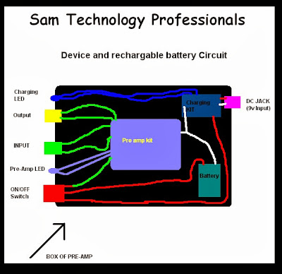
You need to make connection to the battery and the pre amp with this circuit in such a way that if the switch of preamp is turned on then the charger do not charge. Yes..!! you need a two way switch. Following diagram make the idea clear:
In such a way you need to make the connection. This will not mess your pre-amp. And so the pre amps completed. It will become a small portable and rechargeable preamp. And you can build it and show it easily. From me its a perfect DIY preamp for piezo and crystal mics. And it is unique because its a chargeable pre amp.
You can also connect DC jack direct to the battery but above method is 100% safe for battery and amp kit.
So here are the pictures of my pre-amp
 
So have a wonderful project..!!
[Next Projects - Guitar Overdrive Pedal DIY and DC power supply noise filter]