Saturday, 14 December 2013

Build a Guitar Amplifier Easily

So here we have another project that is all about to build a "Guitar Amplifier" which is a portable amp and works with all types of guitar without a pre-amp.
As we know that the OP-Amp amplify the signals such as LM386 so this is able to work as preamp and amp.
So if we add a circuit of lm386 preamp and lm386amp it will become a fantastic guitar amp. Here is a schematic i designed.

This is hard to design but it works 100% perfect with all types of guitar. And all the parts i have used in its design are easily available in the market.

Components Required:
  • 2 - IC LM386
  • 2 - Capacitors 10uf
  • 1 - Capacitor 100uf
  • 2 - Capacitors 0.0047uf [Code 473J or 473K]
  • 1 - Resistors 100 Ohm
  • 1 - Resistor    10  Ohm
  • 1 - Potentiometer 10K Ohm 
  • 1 - LED

It will work with small and large speaker but it is not suitable for too much small speakers.

Q: Do we have a video tutorial and demo about it..???
A: Yes , We do have a tutorial and demo about it at our YouTube channel and link to its video is written below.:
How i built it...??? 
I used a wooden box and did few things to it which are clearly shown in the images below:

And after all the thing done i just packed it and tried to color it with black,yellow and red colors. I tried to write something but i am not good in drawing or designing the outside and that's why an airplane i built was crashed (because of the dry paint drop was stuck in the elevator)....LOL...!!
And here are the pictures when i finished it.
So if you like to create a guitar amp then you don't need to wait more download the circuit and start creating it. I believe you're gonna love this project. And also share your questions and feedback with me.
[Next project will be about a OverDrive Guitar Pedal]

Tuesday, 10 December 2013

Dynamic Mic Pre-Amplifier

This is a latest design of a Dynamic Mic Pre - Amplifier and it works 100%. I also posted a video on YouTube about its working and how i build it.
It is based on a single transistor that is an NPN  BJT transistor C9013. There are many other transistor what you will find in wide variety but this has some different feature. I have tested 2N3904, 2N2222, KT312, C945 and BC547 but all of them don't works like this one. And this transistor gives the good gain for the Dynamic Microphones. 
Here is its circuit schematic i tried to make it work with 5v you can also use a 9v battery but connect positive of your battery and positive of pre-amp through a 100 Ohm resistor (0.25 W) You'll be able to make it work with 9v also. Also by using some circuits like voltage drop etc you can also use it with power supplies of other voltages. 

This schematic is the our basic schematic and it is just a pre-amp for the dynamic microphones. This also works well with long ribbon microphones or other that has impedance about 700 Ohm. It is not suitable for the high impedance like piezo-pickups and crystal microphones. I'll post circuits for Preamp of Piezo Pickups and crystals microphones later.


Here is its little modification. I just added a potentiometer to it. As you can see clearly that the output of our basic circuit is just connected to the wiper of 10k potentiometer and left end is connected to ground and one end is for the Output.


Remember that use battery if you don't know about how to clean a supply, i'll make a post about it also very soon.
Here are the stuff required for this pre-amp:
  • 1 - Resistor 220K Ohm
  • 1 - Resistor 330 Ohm
  • 1 - Resistor  1K Ohm
  • 2 - Capacitors 10uf    (Usually they comes with 50v but you can use a 16v or 25v cap also)
  • 1 - Capacitor    100uf  (220uf or 470uf will also work, but voltage should be at least 25v)
  • 1 - Toogle Switch
  • 1 - BJT Transistor C9013 (Here is its date sheet)
  • 1 - Potentiometer   10K Ohm   [Linear or audio both will work  (Optional)]
  • 1 - LED    (Optional it isn't necessary) 


 So what do you think about it..?? Just create and see how good it works. Also you can give it a cool look. You can create it in a beautiful way. If you still have a problem then check out this video tutorial it tells about its working and how i created it and how it looks like. And you'll see the gain in the software "Audacity" which is a freeware wonderful software. You can also download it but it is for windows pc only.

If you are a beginner then make sure you have checked our latest tab named "Beginners" there are many useful information on this tab about how to read symbol what is resistor and capacitor looks like etc.

So here is the video tutorial of this Pre-Amp
 The audio in the video is recorded by this pre-amp. Specially listen to the closing speech in this video.
I know someone who will think to create this pre-amp will also think for what purpose it is suitable. Well if you have a "Ultra Clean Power Supply" and you have no noise you can use it for any purpose like "Recording Songs", "Recording Instruments with dynamic mic" "Live Performances", "Live Broadcast". And i am you're gonna love its output. Well i can add more things in it like equalizer etc but these things are also available in the PC suits so creating them is a useless thing. Well i will take a look on it.

And HEY...!!! Don't forget to give me your feedback. You are free to comment here without signing up of logging in. Also use my contact form to send me E-mails directly. 

Tuesday, 26 November 2013

Electric Field Detector

Hi guys..!! Today i am posting an other circuit that is an "Electric Field Detector". 
It is a wonderful project and i designed it 7 years before for my school project. And it worked very well. I still have that and it is working well. I was about to fill the target of 500 circuits based on 2N3904 and i was awarded by my teachers for this circuit and an InfraRed interruption Switch of Burglar alarm circuit.

Well here is its basic circuit. It is based on three transistors and three resistors, one led and a battery.
Later i'll be posting its modified circuit diagram. I did its modification and made it about 30 millions gain. And that modification will detect electric field and tell you about how much electric field is detected. So visit this blog regularly..!!

You can click on this circuit to enlarge this schematic.

Components:
  • 3 - Transistors  = 2N3904      [Alternative = KT312, BC547, 2N2222]
  • 1 - Resistor      = 100k Ohm   [0.25Watt] 
  • 1 - Resistor      = 1M   Ohm    [0.25Watt]
  • 1 - Resistor      =  220  Ohm   [0.25Watt]
  • 1 - Small Piezo-buzzer and LED
  • 1 - Toogle Switch (Or Any Type of switch)
  • Probe                   ( Or Twist any hard copper wire to make a probe. It will work too.)
Beside these components a 9v Battery or a DC power supply is also required. Or you can use 3 small button battery of 3v in series that will make 9v too.


Friday, 26 July 2013

Simple and High Quality Audio Amplifier:

 So here is another circuit. I have posted the pictures of what i built using this circuit. Its a tiny amplifier schematic that can be used to drive the large speakers. I 've shown in the diagram the lm386 which is an opamp available in DIP and SMD. This chip is fantastic thing & very popular everywhere. It can be found in any radioshack or our local electronics stores. Most of the mp3 players coming from china now a days uses this amp. Given below is the schematic that is the basic version i designed and below this there is the modified version with explanation. 

You can click on the image to enlarge it. Well here are some important things i think i must mention here. So please read them if you are a beginner :

  1. The Capacitor 47nf    = 0.047uf = 473pf
  2. The Capacitor 100nf  = 104pf
  3. Potentiometer must be of 10k if you bring 50 k then put a 102pf capacitor between wiper of potentiometer and ground.
  4. To get some extra gain put 10uf  capacitor (of 50v) between pin 1 and 8 of IC.
Components Required:
  • IC - LM 386 or C386
  • Capacitor 100nf
  • Capacitor 473pf
  • Capacitor 330uf at 16v
  • Capacitor 100uf at 35v
  • Resistance 10 Ohm  [ 0.25Watt ]
  • 9v Battery or a 9v DC clean power supply
I never liked the diagram people provided on the internet that is quite similar to the above one. Because it contains a huge noise and distortion signals at output. Also 47nF and resistor 10R in series between pin6 and ground which is used to prevent noisy signals found to be useless. So after a lot of experiments i came to a decision that just a single 100nF capacitor was fine to bypass those unwanted noisy signals. Below the modified version is given:

 Firstly, lets discuss the input. So, in the previous circuit we used potentiometer and here i am using two 1K resistor parallel? No, they're not parallel. They are the left and right channels for input. This is due to many persons asked me about "how to use it to listen stereo?" and so, i simply added a mixer circuit at input using 1K resistor (yes its simple and cheap method to do so, however there are also several other ways).  Now you can listen to the good to both channels of stereo audio but not like stereo effect. Shorting the left and right channel is not suitable and recommended method. Just use this method which can be called a passive audio mixer in order to mix both of the channel of incoming audio. However you won't be having a stereo output as there is just a one speaker and just one input at IC lm386 pin 3 (But you can use two amp-circuits for that). But i think that it is just fine if you're about to listen to the audio just for fun. So, in the above given schematic you can still add a stereo potentiometer if you want. A value of 10K would be fine will provide you good range of setting the input gain. 
I saw many people use a 10uF capacitor between gain pins 1 and 8 of IC386, i don't recommend that because i experimented on it resulted in blown chips and one time it caught fire on the breadboard which caused my beautiful and expensive breadboard look horrible. The amp chip was draining alot of current than expected in order to increase the gain however i didn't have a low current power supply so it got blown. Anyways;

Circuit on vero-board can be more compact as follow:


Keep the wires that you use to create connection between IC pins and other components as shortest possible. This would prevent unwanted noise from surroundings or any electric device near it. Or maybe it caught the radio frequency sometime. 

Components Lists:
LM386
8 pin DIP socket
1000uF-16v Capacitor
100nF ceremic Capacitor (Code for which is 104)
2pcs 100uF - 16v Capacitor
2pcs 1K resistors 0.25W 

To build a good amplifier never salvage capacitors. Use new one with accurate values mentioned. In order to make it sound clean forever use a metal project enclosure box and never forget to connect the amplifier circuit's ground wire to it. 
Good Luck.! And Have a wonderful project. (Y)

Friday, 12 July 2013

Electronics Circuits,PCB Layouts and Projects


© We Are Promoting The World.

I created many Pre-Amplifiers and Audio Amplifiers mono type and stereo type.I use electric box mostly to fit my circuit completely. I design my circuits at computer or sometime when I have no time to spend on computer I just do it my self with the help of a permanent market. After that I use my hand drill to create holes in my pcb to put the components in it for soldering.

So here are my some captured images of the place where I create and do fun with all these stuff.

We provide every circuits,pcb layout free and respond quickly to your every asked question. We are an independent group so we need your support to continue this site.
Please donate by clicking the button to help us keep this service alive.


HQ Stereo Audio Amplifier:

Here is the circuit of HQ stereo amplifier i created this amp by spending 5 hours.  This is an IC TDA2822 based amplifier. The sound of output has no noise. And the wonderfull thing about it is that it is capable of playing sound on large speakers. This is not like other ordinary amp that has only one speakers output for stereo. In this amplifier you'll attach left and right speakers separately in their pins. Here is the circuit schematics. Have a look of it

This is the circuit schematics. You can see there are two speakers place here in this circuit. Also check its PCB design, Yeah..!! Its PCB layout is also available for you to download 100% free. Circuit is too simple to create so don't hesitate to create it by your hands. Go to our Download Page to download this circuit,PCB Design with pcb layout and components details. 

Don't forget to download it with complete pack. Our download page is 100% free for you. Request for more circuits. We post every day, we update ever day..!!
 

Dynamic Mic and Guitars Pre Amplifier:

This pre-amplifier has some extra qualities that it has a potentiometer to set the gain. It is applicable at 30v DC but DC must be supplied by a battery or clean DC power supply other wise it will create noise in the output.
I use it through line in of my computer to record sometimes. Its perfect for resonator guitars and some other semi acoustic guitars etc.
  There is a potentiometer you can see having a black color cap on it. 
And its front part. It looks cool when I close this electric box with a simple plate that has no hole for any electric switch. All the holes I create in it are firstly drilled by my hand drill and then widen by some screw drivers. That’s easy and quick. You can do by changing machines jumb from pcb drill to electric drill for widening the holes by wandering here and there its crazy.

My First Stereo Audio Amplifier:

This is my first handmade stereo audio amplifier. I designed its circuit myself. It is based on an IC LM386 or I could also use C386 for this circuit. Let’s have a look of it.
You see that it is also created in an electric switches box. Well the circuit is not too much complex as it seems. I just added a DC filter circuit in it to make it sound clear. Now it can be use by any ordinary DC power supply. There are two potentiometers (Both are of 10k Ohm) for controlling left and right channel. Currently I have attached them to my 3 inch 50W and 4 ohm speakers. You can use it with any type of pro speakers. In this picture the input side (as you can see where the bulb is lightening) is given by my computer soundcard. Yeah I am playing through my computer. Here you can see the picture of the speakers I attached.


They are professionally fitted in a wooden box. The size is almost 3inch of each speaker. You can download its circuit schematics with component details and pcb layout. Click on our download button above.

Bread Board Circuit Testing:

I mostly test my circuits on breadboard. And many times I get better result. I am tired f using vero boards now they are not much helpful at all now because I am now addicted to Printed Circuit Boards.  So have a look of my stereo amplifier using an IC TDA2822 and some caps and resistor. Firstly tested on breadboard then created on PCB.

Sometime they become silent and that’s embarrassing encountering the problem. I start testing through voltmeter or sometime I understand myself what is the exact problem.

Mechanical Works:

We must keep in mind when we start our working in this beautiful field of electronics that we know some basics of mechanical work. Like how I fit the circuit in the electric boards. From where this idea comes that I must put them in that box. 


MIC And Guitar Mixer:

I created a Microphone and guitars mixer. That has low and high pass filter option. It is great helping material in recording through Dynamic Microphone, Semi-Acoustic Guitars and Resonator Guitars etc. Have a look of the circuit schematics I designed.
Here S3 is output attention selector and S3 is low-pass and cut-off frequency filter. The transistor you’re looking in this schematic is a JFET ( Junction Field Effect Transistor) its value is “BF245B” or you can also use “BF245C”. 

 
Have a look of its PCB structure given below:


Its PCB Layout is also available for download. You can get the download link by clicking Download Button on this site.
Take a look of its real-time pcb created with the components not soldered.


Another MIC Pre-Amplifier:

Here is another device which is my handmade. I designed its circuit and it worked well. Just take a look how I build it in a plastic box.

 And take a look of its pictures while it is working.


As you can see there are two inputs that seem to be dynamic microphone inputs and two yellow females as you can see are for the output. The two input both are not for the dynamic microphone. But in fact one is for dynamic and one is for condenser (Elektrek) microphone. It is applicable at 9v battery or a clean 9v DC power supply.
You can see right there in the picture that the bulb is lightening when the switch is turned on.

My Radio Controlled Doorbell:


Yeah this was the fantastic project for me to do. This doorbell has three sounds. We can select a sound from the button at the side of the bell. The ringer is to set into the house by putting two AA size 1.5v batteries in it. And remote consist a micro 12v Cell as you can see in the pictures below. This project was created because I when get late from my job I use it to make my home mates sure that I am standing out there.

The boxes you can see in these pictures are taken from the market where mostly RC devices are being prepared. But I got this one from scrap because every shopkeeper was about to give at least 20 boxes.

Stuff That I Use:

There are some basic things that I use most I have captured their images too that are  PCB drill machine, Soldering Iron, Soldering Wire, Paste, PCB’s, and other things like this. 
I also use some programs that have ability to create a Circuit on Breadboard in 3D and export as an image to show to your friends and have fun. Here is an example of an audio amplifier on a 3d breadboard.

My TV Magic Box:

There was a time when I was having a TV which contains only 30 channels capacity. So I created a magic box device that provides above thousand channels to any TV. I used 7 segments, Transistors, Capacitor. And according to me it was a simple project to do. So take a look of it:

I tested it on breadboard some components that I drawn wasn’t necessary so I left those holes.

My Rechargeable Emergency Light:

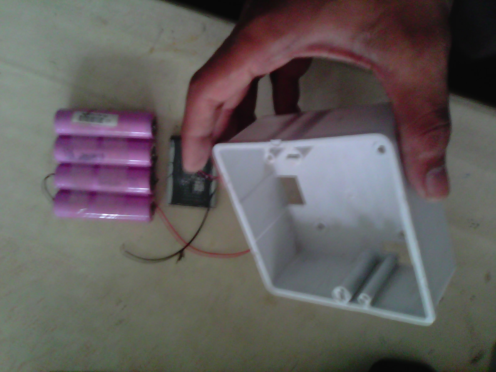
I used two high intensity LED with a 3.7v mobile battery which provides 1600mAh. It shines like a tube light and it is good for room when your electrical power is gone. Have a look:
                        
There is a golden colored battery behind the plastic. You can see it in the 2nd picture.

My Camera Repaired:


I got a digital camera that was a gift at my 8th birthday. The problem happened in its display where it shows the number of captured images. When I took it to the market the repairer said that its an old model we do not repair such types in fact we don’t know much about it. So I repaired it my self. Now it works fine. It has ability to capture 60 images then you can get them through data cable by transferring to your computer.

This is the picture when I opened it and now it is packed in its casing.

Where I mostly Draw Circuits:

The best place where I spend much time while I am about to create something new. It is my whiteboard. It is 6 years old but it looks new. Here are some pictures captured:


This whiteboard is fitted on the wall so when i draw the circuit i need a large chair.

Do You Want A Circuit …???

I love to spread my knowledge all over the world. So you can contact me if you need any circuit or help.
Please let me know if you need any circuit or a pcb layout if you want me to create, no problem I’ll do that for you. Click on the contact button of this site.
Create something special and spread your knowledge to the world. Have a Great Day..!!
Thank You..!!
Asim Ali  (King of Electronics)

©(Sam Technology Professionals – We are promoting the World)